[Create compound channel grid]
Description: Creates a grid that has lower channel, by defining grid creating region and lower channel region. Figure 284 shows an example of created grig.
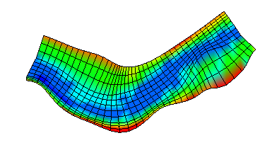
Figure 284 Example of grid created by [Create compound channel grid]
After selecting this algorithm, define grid creating region as a polygon in canvas, by mouse-clicking. Finish defining by double-clicking or by pressing Enter key. Next, define low lower channel as a polygon in the same way. Next, define center line of grid as polygonal line. Figure 285, Figure 286, and Figure 287 show examples.
When the center line is defined, the [Grid Creation] dialog (Figure 288) will open. Input the grid creating condition and click on [OK] to create a grid.
Center line has to be inside low water channel region, and low water channel region have to be inside grid creating region. If this condition is not matched, a warning dialog will be shown, and you’ll have to modify conditions before creating a grid.
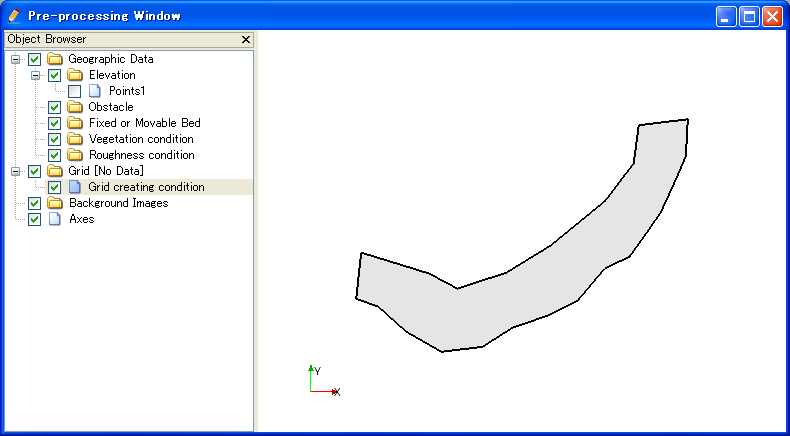
Figure 285 [Pre-processing Window] after defining grid creating region
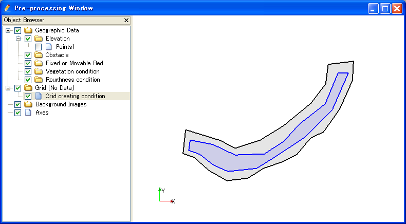
Figure 286 [Pre-processing Window] after defining lower channel region
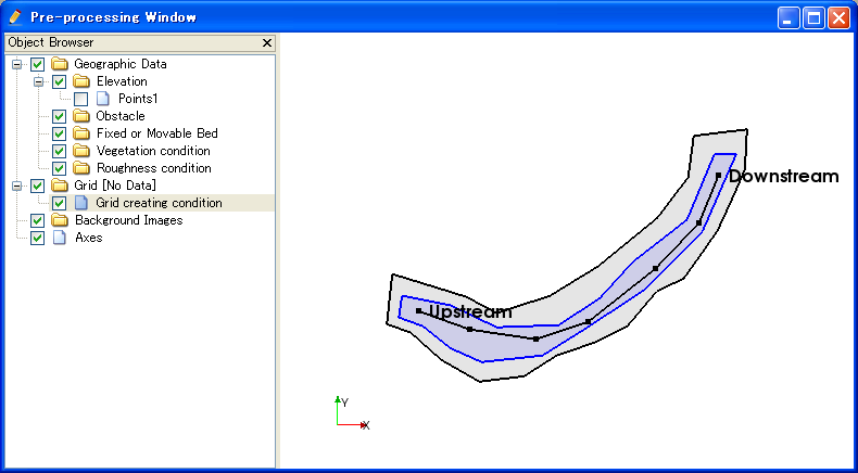
Figure 287 [Pre-processing Window] after defining grid center line
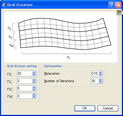
Figure 288 [Grid Creation] dialog
Regions and center lines can be edited using the menu items explained in Menu items.
[Add Vertex] (A)
Description: Adds a vertex to the region (or center line) that is currently selected.
When you select [Add Vertex] and move the cursor to the edge of region (or center line), the cursor changes to that shown in Figure 289. Left click on the line and drag it to add a new vertex. The vertex is placed where you release the left button.

Figure 289 Mouse cursor when possible to add a vertex
[Remove Vertex] (R)
Description: Deletes a vertex from the region (or center line) that is currently selected..
When you select [Remove Vertex] and move the cursor onto the vertex you want to remove, the cursor changes to that shown in Figure 290. Left clicking will remove the vertex.

Figure 290 Mouse cursor when possible to remove a vertex
[Edit coordinates] (C)
Description: Edits the coordinates of the vertices of the region (or center line) that is currently selected.
When you select [Edit Coordinates], the [Polygon Coordinates] dialog (Figure 291) will open. Edit the coordinates and click on [OK].
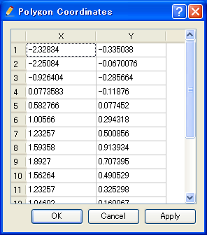
Figure 291 [Polygon Coordinates] dialog
[Reverce Center Line Direction] (E)
Description: Reverce the center line direction. Figure 292 shows an example. Note that the “Upstream” and “Downstream” are reversed.
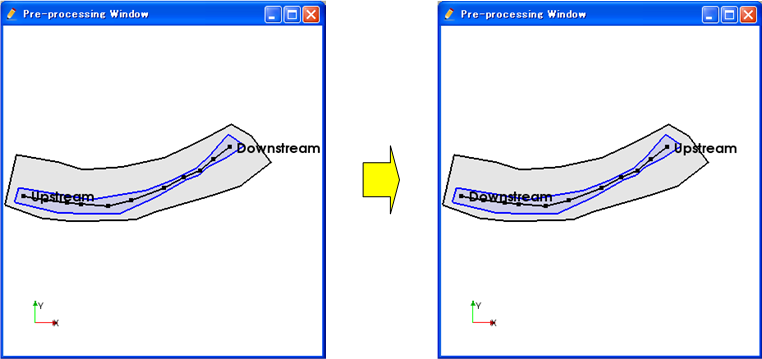
Figure 292 Example of center line before and after reversing
[Reset to Default] (D)
Description: Discard the grid creating condition and reset to the default status.