[Create grid from Polygonal line and width]
Description: Creates a grid that smoothly follows a Polygonal line. Figure 264 shows an example of a grid created by this algorithm.

Figure 264 Example of grid created from Polygonal lines and widths
After selecting this algorithm, click on the canvas to specify a few points on the centerline of the grid. To finish, press the Enter key or double click. Figure 265 shows an example of the display when the grid centerline has been set.
After the centerline has been set, select [Create Grid] from [Grid] on the menu. The [Grid Creation] dialog (Figure 266) will open. Click on [Apply] to see the resulting grid, adjust the input data and click on [OK].
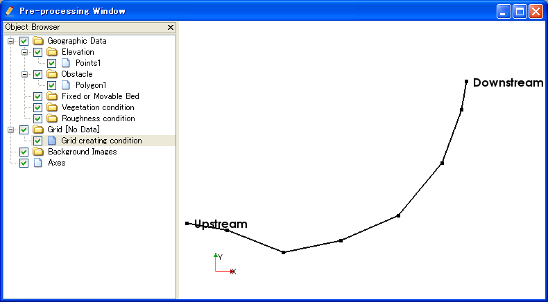
Figure 265 Example of display after the grid centerline has been set
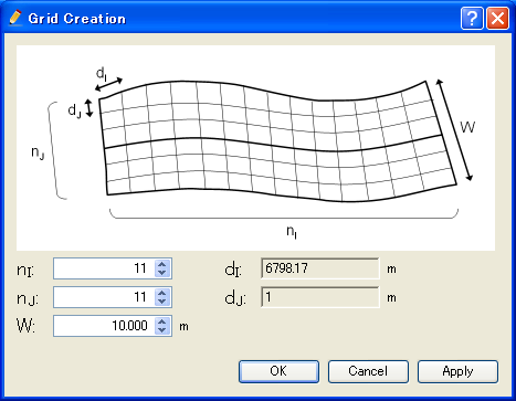
Figure 266 Example of the [Grid Creation] dialog
To edit the vertexes of the centerline, select from the menu shown in Table 27.
[Add Vertex] (A)
Description: Adds vertices to the centerline.
While selecting it, move the mouse onto the centerline. The mouse cursor changes shape as shown in Figure 267. Left clicking adds a new vertex.

Figure 267 Mouse cursor display when adding a vertex is possible
[Remove Vertex] (R)
Description: Removes a vertex from the centerline.
While selecting it, move the mouse onto the centerline. The mouse cursor changes shape as shown in Figure 268. Left clicking removes the selected vertex.

Figure 268 Mouse cursor shape when removing the vertex is possible
[Edit Vertices Coordinates] (O)
Description: Edits the coordinates of the vertex of centerline.
When you select this, the [Polyline Coordinates] dialog (Figure 269) will open. Edit the coordinates and click on [OK].
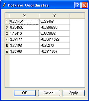
Figure 269 [Centerline Coordinates] dialog
[Line Direction] (E)
Description: Reverce the center line direction. Figure 270 shows an example. Note that the “Upstream” and “Downstream” are reversed.
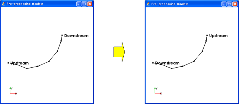
Figure 270 Example of Center line before and after reversing
[Remove Centerline] (C)
Description: Removes the centerline and restores the condition immediately after the algorithm was selected.
After removing the centerline, click on the canvas to define the centerline in the same way as the first centerline was defined after selecting the algorithm.