[Create grid from polygon shape]
Description: Specifies the Polygonal area where the grid is to be created, and generates an unstructured grid. You can also specify a re-division area and an obstacle area within the area as grid creating condition. Figure 334 shows an example of a grid created by this algorithm.
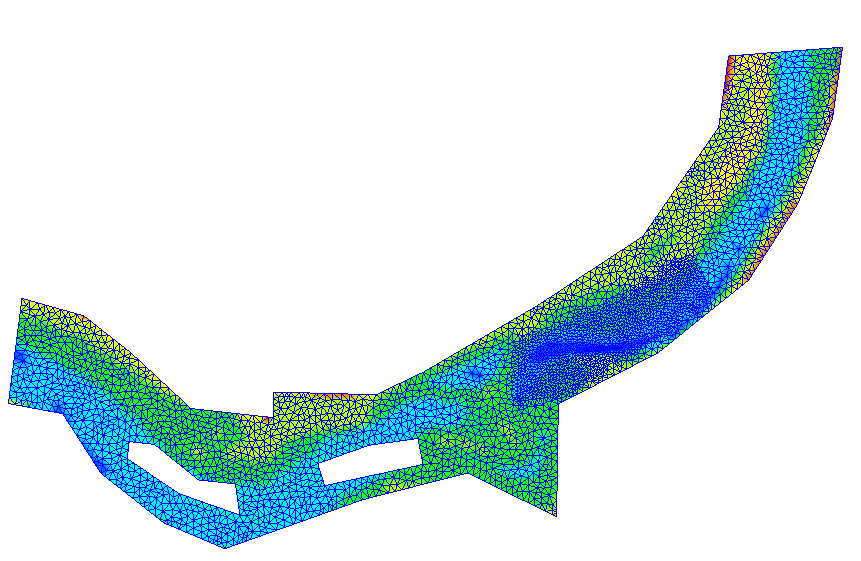
Figure 334 Example of a grid created based on the shape of the Polygon
After selecting this algorithm, click on the canvas to specify an area for creating the grid by Polygon. To finish, press the Enter key or double click. Figure 335 shows an example of the display after specifying the grid creation area.
After setting the center line, select [Create Grid] from [Grid] in the menu.
The [Grid Creation] dialog (Figure 336) will open. Specify the area where the grid is to be made and click on [OK]. The grid is generated according to the division points.
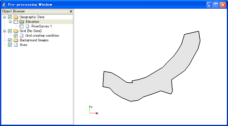
Figure 335 Example of the display when an area for grid creation has been specified
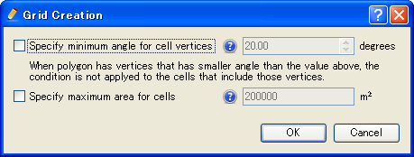
Figure 336 [Grid Creation] dialog
[Add Refinement Region] (R)
Description: Adds a refinement region to the grid creation area. The maximum area of cells can be set for the refined region. It is possible to set a fine (or coarse) grid exclusively in the refinement region. The refinement region is displayed as a red polygon.
After you select [Add Refinement Region], click on the canvas to define a refinement region as polygon. Finish defining by double-clicking or by pressing Enter key. The [Refinement maximum area] dialog (Figure 337) will open. Set the maximum area of the cell and click on [OK].
Figure 338 shows an example of the refinement region, and Figure 339 shows the grid created under this setting.
From iRIC 3.0, it is now possible to define refinement Regions inside a refinement region. There is no limit about the number of recursion. Figure 340 shows an example.
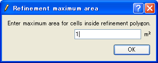
Figure 337 [Refinement maximum area] dialog
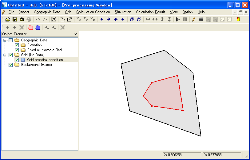
Figure 338 iRIC window after defining refinement region
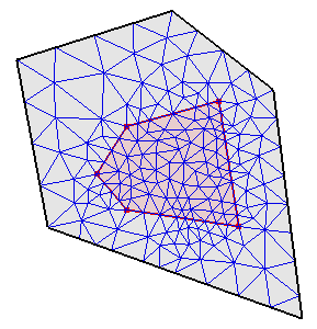
Figure 339 Example of a created grid
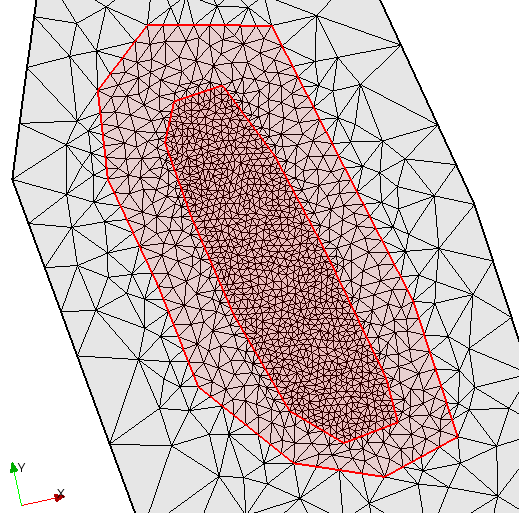
Figure 340 Example of defining refinement region inside refinement region
[Add Hole Region] (H)
Description: Adds a hole region to the grid creation area. The hole region is displayed as a blue polygon.
After you select [Add Hole Region], click on the canvas to define a hole region as polygon. Finish defining by double-clicking or by pressing Enter key.
Figure 341 shows an example of the hole region, and Figure 342 shows the grid created under this setting.
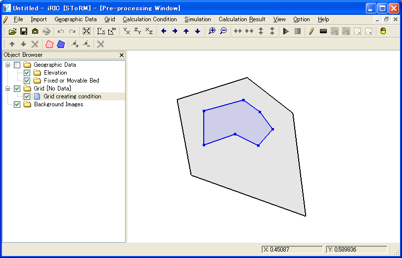
Figure 341 iRIC window after defining hole region
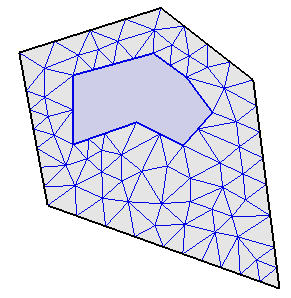
Figure 342 Example of a created grid
[Add Break Line] (B)
Description: Adds a break line to the grid creation area. The break line is displayed as a bold line
After you select [Add Break Line], click on the canvas to define a break line as polygonal line. Finish defining by double-clicking or by pressing Enter key.
Figure 343 shows the grid created with a break line.
With iRIC 3.0, it is now possible to define a break line that run over the grid region. Figure 344 shows an example of such a case.
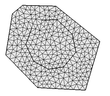
Figure 343 Example of a created grid with a break line
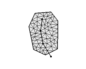
Figure 344 Example of a created grid with a break line, that run over the grid region
[Add Vertex] (A)
Description: Adds vertices to the selected region or break line.
Select this and move the cursor to the Polygon line. The cursor changes to the graphic shown in Figure 345. Left click on the line and drag it to add a new vertex. The vertex is placed wherever you release the left click button.

Figure 345 The mouse cursor display when adding a vertex is possible
[Remove Vertex] (R)
Description: Deletes the vertex of the selected break line.
When this is selected and you move the cursor onto the vertex of the Polygon, the cursor shape will change (Figure 346). Left clicking will remove the vertex.

Figure 346 The mouse cursor when removing the vertex is possible
[Edit Coordinates] (C)
Description: Edits the coordinates of the selected region or break line.
When you select [Edit Coordinates], the [Polygon Coordinates] dialog (Figure 347) will open. Edit the coordinates and click on [OK].
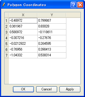
Figure 347 [Polygon Coordinates] dialog
[Edit Maximum Area for Cells] (M)
Description: Edits the maximum area of the cell in the selected, refinement region.
When you select [Edit Maximum Area for Cells], the [Refinement Maximum Area] dialog (Figure 348) will open. Edit the maximum area and click on [OK].

Figure 348 [Refinement maximum area] dialog
[Redivide Break Line] (R)
Description: Redivide break line to control the grid cell length on the break line.
When you select [Redivide Break Line], the [Input divide number] dialog (Figure 349) will open. Edit the divide number and click on [OK].
Figure 350 shows an example of redividing a break line.
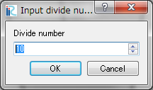
Figure 349 [Input divide number] dialog
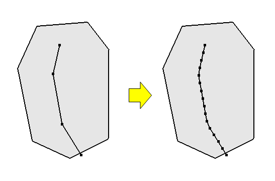
Figure 350 Example of redividing break line
[Delete Region or Break Line] (D)
Description: Deletes the selected Region or Break Line.
When deleting a Polygon in an area where a grid has been created, a new grid creation area can be specified.
[Reset to Default] (R)
Description: Discards the grid creating conditions and restores the default state.