Menu bar, Toolbar and Status bar
The menu bar and the toolbar have the characters explained below.
Toolbars
The following three toolbars are available:
Main Toolbar
Operation Toolbar
Animation Toolbar
For the functions of each toolbar, refer to Table 2.
Item |
Functions |
Displayed when |
|---|---|---|
Main Toolbar |
Handling of files, canvas display, solver launching and window display |
Always |
Operation Toolbar |
Operations that are possible for items selected in [Object Browser] |
When the [Pre-processing Window] is active |
Animation Toolbar |
Moving between timesteps of simulation results |
When the Post-processing Window or the Graph Window is active |

Figure 3 Main Toolbar
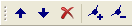
Figure 4 Operation Toolbar

Figure 5 Animation Toolbar
Status bar
Figure 6 shows an example of status bar.

Figure 6 Status bar
The functions available on status bar are described below.
Scale
Displays the scale of the display in the currently active window.
Clicking on it brings up the dialog shown in Figure 7, where you can change the scale by specifying a value.
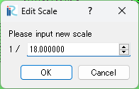
Figure 7 Scale editing dialog
Angle
Displays the angle of rotation of the display in the currently active window, defined as 0 when the x-axis is facing right and counterclockwise from there is the positive direction.
Clicking on it will bring up the dialog shown in Figure 8 where you can change the angle by specifying a value.
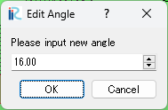
Figure 8 Angle editing dialog
Size
Displays the size of the drawing area in the currently active window.
When clicked, the dialog shown in Figure 9 will appear, allowing you to resize the window by specifying width and height values.
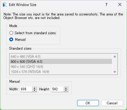
Figure 9 Window size editing dialog
Note
The size displayed and edited by this function is the size of the area in the currently active window where the screenshot will be saved. It does not include the size of the area of the object browser, toolbar, etc.
X, Y
Displays the position of the mouse cursor in the currently active window.
CS (Coordinate system)
Displays the coordinate system specified in the currently open project.
Clicking on it will bring up the dialog shown in Figure 10, where you can change the coordinate system.
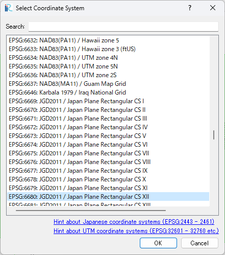
Figure 10 Select Coordinate System dialog