Editing [Lines]
Description: Define geographic data defined as Lines. Figure 235 shows an example of [Lines].
Figure 235 Example of the [Lines]
Note
Geographic data group in which [Polyline] can be defined
[Polyline] can be added only to Geographic Data group [Reference Information].
Note
[Polyline] on [River Cross-section Window]
On [River Cross-section Window], the intersection points between [Cross-section] and [Polyline] are displayed.
Using this function, you can add [Polyline] as reference information on [Pre-Processing Window] first, and you can edit the cross-section shape, considering the [Polylines] that corresponds to roads, for example.
Figure 236 shows an example of [Polyline] shown on [River Cross-section Windo].
Please refer to [Generate point cloud data] for the detail of [River Cross-section Window].
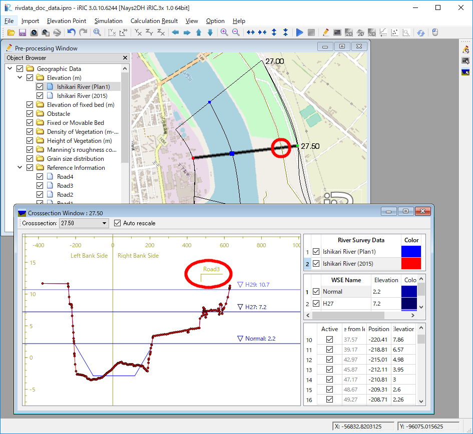
Figure 236 Example of the [Polyline] displayed on [River Cross-section Window]
Note
Drawing charts with calculation result interpolated on polylines
iRIC 1.0.14 and later can draw charts with calculation result interpolated on polylines. Please refer to [Graph Window] for detail.
[Lines Attribute Browser]
When [Lines] data is selected in the [Object Browser], [Lines Attribute Browser] is shown. Figure 237 shows an example of [Lines Attribute Browser]. The list of columns in [Lines Attribute Browser] is shown in Table 22.
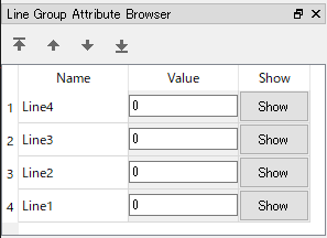
Figure 237 Example of [Lines Attribute Browser]
| Column name | Description |
|---|---|
| Name | The name of lines. You can edit the values. |
| Value | the valud of lines. You can edit the values. |
| Show | When clicked, the clicked line is shown in the center of the drawing area. |
Selecting operation
For [Lines], user can select multiple lines at the same time. the selected lines can be deleted or sorted with one operation.
User can select line with the two ways below:
- Mouse operation: Draw boundary box by left-dragging, and all lines sorrounded by the box are selected.
- Attribute browser operation: Click on items in [Lines Attribute Browser], and the clicked item is selected. You can select multiple items, by clicking with pressing Ctrl key.
[Add New Polyline]
The procedure to add a new Polyline is as follows:
- Select the [Reference Information] under [Geographic Data] in [Object Browser] (Figure 238).
- The operation below adds a new Polyline to [Object Browser], and that Polyline is selected.
Menu bar: [Geographic Data] (E) –> [Polyline] (L) –> [Add New Lines]
- On the canvas, add vertices to the line by left clicking (Figure 239).
- Double click or press the Enter key to complete defining the Polyline.
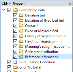
Figure 238 Example of the [Object Browser] display
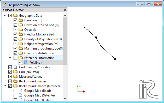
Figure 239 [Pre-processing Window] when the [Polyline] is being defined
[Add New Line]
Description: Adds a new line to [Lines] data.
[Add New Polyline] adds a new [Lines] data. On the other hand, this function add an new Line to the [Lines] data that already exists.
The steps to define a line is the same to [Add New Polyline].
[Edit Value] (V)
Description: Edits data value on the Line.
When you select [Edit Value], the [Edit Elevation value] dialog (Figure 240) will open. Input a new value and click on [OK].
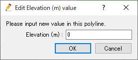
Figure 240 The [Edit Elevation value] dialog
[Add Vertex] (A)
Description: Adds a vertex to the [Polyline].
When you select [Add Vertex] and move the cursor to the edge of [Polyline], the cursor changes to that shown in Figure 241. Left click on the line and drag it to add a new vertex. The vertex is placed where you release the left button.

Figure 241 Mouse cursor when possible to add a vertex
[Remove Vertex] (R)
Description: Deletes a vertex from the [Polyline].
When you select [Remove Vertex] and move the cursor onto the vertex you want to remove, the cursor changes to that shown in Figure 242. Left clicking will remove the vertex.

Figure 242 Mouse cursor when possible to removing the vertex
[Edit Coordinates] (C)
Description: Edits the coordinates of the vertices of the [Lines].
When you select [Edit Coordinates], the [Polyline Coordinates] dialog (Figure 243) will open. Edit the coordinates and click on [OK].
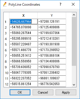
Figure 243 The [Polyline Coordinates] dialog
[Merge]
Description: Merge lines in other [Lines] to this data.
[Select data to merge] dialog (Figure 244) is shown. Select the data to merge, and click on [OK] button.
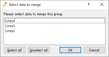
Figure 244 [Select data to merge] dialog
[Copy]
Description: Copy the data to other [Geographic Data] group.
[Select Graographic Data] dialog (Figure 245) is shown. Select the [Geographic Data] group to which you want to copy the data.
Then, [Copy Setting] dialog (Figure 246) is shown. Specify the values of the lines, and click on [OK] button, to finish copying the [Lines] data.
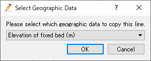
Figure 245 [Select Geographic Data] dialog
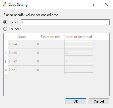
Figure 246 [Copy Setting] dialog
[Color Setting] (S)
Description: Edits the color of the [Polyline].
When you select [Color Setting], the [Polyline Color] dialog (Figure 247) will open. Set it and click on [OK].
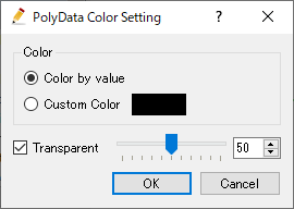
Figure 247 The [Polyline color] dialog